But this blog is about the Ner-a-Car, so here is what has been going on there.
Having shown that the engine can run, there seemed no reason not to put it in the chassis:

I needed to buy some special bolts, as I only have metric in stock. In fact buying imperial bolts in the strange mix of Whitworth, BSF and BA that the machine uses is quite annoying. They are cheap enough, a few quid for a few bolts from eBay, but every time I find a bolt I don't have, I need to wait a few days for an order to arrive.
Unless, of course, I have something close; this is a 3/8 BSF bolt in the middle of becoming a rather shorter Whitworth bolt. (This was a spare cross-shaft bolt becoming a brake plate torque reaction bolt)

Exhaust Silencer
One other thing evident from the test run was how loud the engine is without an exhaust. It might actually be loud with an exhaust, contemporary road tests did complain about the noise.
The exhaust couldn't be finished until the engine was in the frame, as the entry hole has to line up with where the exhaust manifold puts it.
I fitted the manifold, and then iteratively shortened the exhaust pipe until I could scribe around it. I then chain-drilled to the scribing, and cleaned out with a Dremel. (A real one, the cheap one I used to use died. The real one is a much better tool. In fact I leave it hung on a nail behind the workbench permanently plugged in because it is handy so often).

I then made a socket/flange welded to the outer drum, added an outlet pipe, and gave it a coat of barbecue paint.

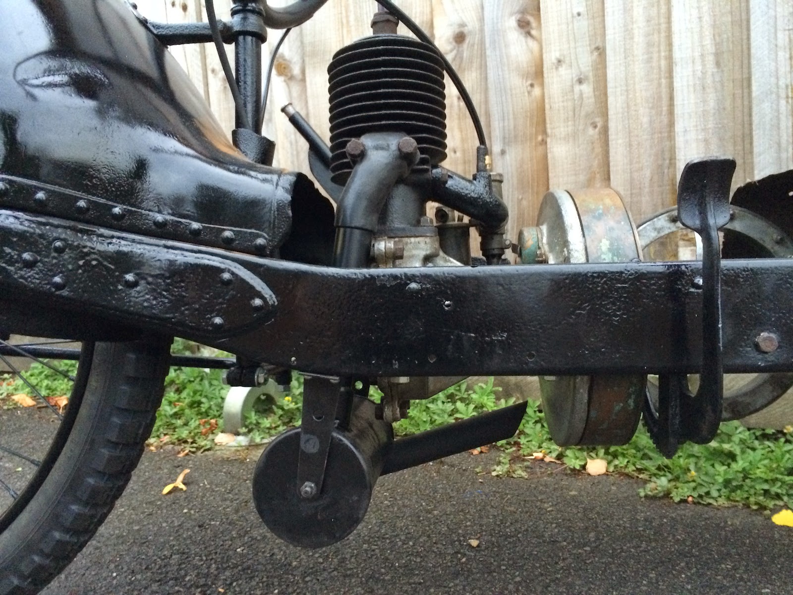
And here it is, in-situ.
Handlebars
The bike did have some handlebars, which is lucky because they are odd. Not any more odd than the rest of the bike, but not the sort of thing you can pick up from Renthal.
The left bar has a twist-grip, which rotates several times on a square screw thread. This pulls a fat cable, which pulls the friction wheel against the flywheel. I initially though that this was missing, but when I cut off remains of the original twistgrip tube (the grips themselves were long gone) it turned out that both halves of the thread were there.
The bars were rather rust-pitted, and in fact the right handlebar end, unprotected by a twistgrip tube, was rather perferous. As it needs to mount an inverted brake lever, so sees some force, I decided to sleeve it up to 1" with a non-twisty twist-grip tube, glued on with Araldite.

To deal with the rust pitting I used "knifing putty" which seems to be little-known, but is ideal for this sort of thing. It is like very thick cellulose paint that goes on with a knife rather than a brush. It dries pretty quickly, and is easy to sand. The picture above shows the bars after being smeared with a second coat of knifing, and the picture below is of it all sanded back down ready for primer.

I needed a new "clutch" cable, but the original one is 1/8" and not easy to find. After trying to get a quote from a specialist, who never rang me back, I decided that I could re-use the original outer (after stripping off the remains of the cotton/shellac(?) covering, and re-covering with shrink-fit tubing.
I found that B&Q sell steel wire rope in the right size. I nearly got it very cheaply indeed, as they originally rang up the wrong diameter, then rang up the wrong length. I managed to persuade them to let me pay 4x what they asked. I am not sure why...
I then needed to spend some actual money. I had already bought the throttle/air levers from eBay. I also needed some replica handlebar grips from Dial Patterns and an inverted brake lever. There are lots of brake levers on eBay, in India, for Enfields. However they don't look quite right, and don't exactly exude quality. Quality is what is exuded by the one I bought from Moto-Phoenix, though.
Rather more for one lever than for a pair from India, but the quality is excellent. It even comes with the right nipple to solder on to the wire. Another nice touch is a segment of a circle that keeps the wire from kinking as the lever is pulled.

Sprockets and Transmission
Fitting the transmission shaft is a right fiddle. There is an actuating arm for the speed control, and a cable for the friction control, and the pull-of spring for the cable, and the support brackets, all to be assembled in the area where the friction wheel wants to be (it has a big spring).

While I had the cross-shaft apart it became evident that the front sprocket was not in great shape, so I made one from a pilot-bore blank. I don't think I could buy the material for that, even if I did want to put my own teeth on. I made a very boring video of the process of making the sprockets as a demonstration of the lathe-macros that I wrote for LinuxCNC.
In fact I made quite a lot of sprockets, and sold them on eBay to other owners. I sold 11 in a week, but I don't think that is a sign that I can expect to sell 500 a year. Market saturation looms.

And with sprockets sorted out, the bike can have a chain too.

Stand
The eagle-eyed might have spotted that I have been supporting the bike on a modern paddock stand. There is an original stand in the pile of bits, but very much past its best.
The stand is made of a steel U-section. 3/4" wide. I couldn't find a way to buy that, so I ended up getting box section and cutting the top off.

The long length of box made an effective coolant gutter, which is why there is a bucket hanging on the end.
To bend the U to shape I made a bending jig out of an MDF board and sime bits of ply cut to shape and screwed on. Firstly it was fitted to the original:

Then the first bend was made with the relevant corner block removed:

Then when the U-shape is bend down far enough, the block was re-attached and the upwards bend performed.

And the final shape:

I use computer-aided manufacturing for the top brackets. Though the computer aid was rather limited.
From a CAD model of the required shape I printed out the flat-sheet pattern on paper, and glued that to a sheet of steel. (I tried to use black paint as glue at first, but it don't work, hence the mess).
Cutting round the shape, drilling the holes, then bending at the place that the computer said gave me two mirror-image brackets. The computer is much better at bend-allowance calculation than I am.

With the hinge bracket riveted on, and a brace strap also rivetted on (I am really glad I made the hydraulic rivet squeezer) the final result looks like this (with the original one underneath for comparison).

And now:
It looks like this: (except that the paint on the stand isn't done yet, so it's not fitted)

No comments:
Post a Comment